Among the simpler pieces of dimensional measuring equipment used regularly in metrology is the micrometer. I could get technical with Abbe’s principal and discuss the collinear requirement of the measurement direction, but I’d rather give you simple useful information. Let’s start.
A micrometer is measuring a diameter feature using two anvils, one stationary, and one that moves on a “lead screw.” This is usually a one inch length precision thread that allows you to move that second anvil, often called the “spindle anvil” until it touches as required and you can make your measurement.
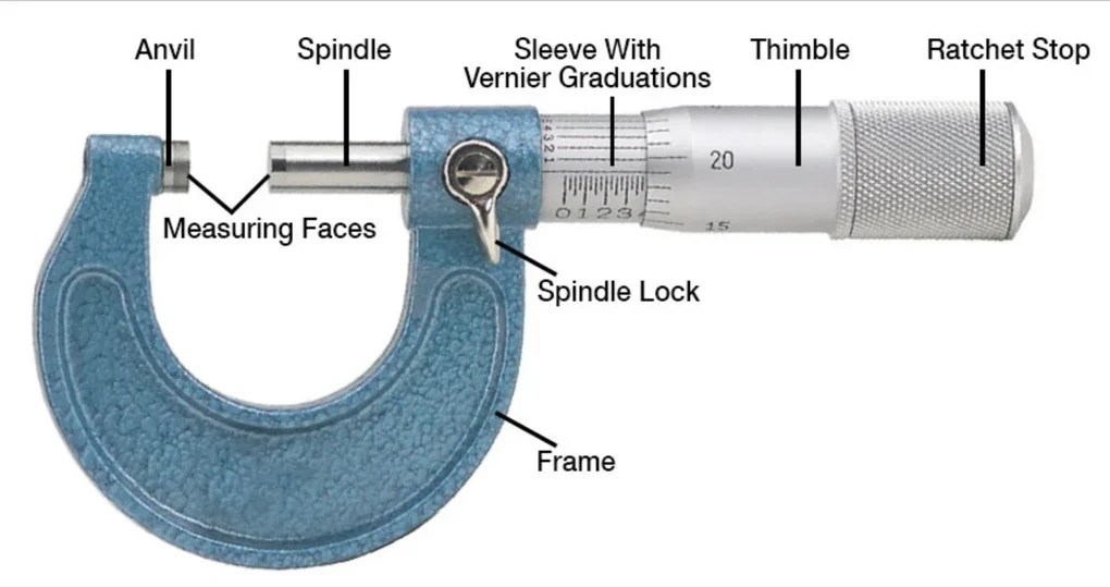
Above is a picture of a generic outside micrometer that shows you all of the important parts and features. Not pictured but common would be black plastic along the bottom the frame called a “heat shield” that protects the frame from heat transfer and thermal expansion from being held.
You can see looking at the measuring faces that these are carbide faced anvils. Carbide is a tougher, more scratch resistant material that is also more stable for temperature deviations. Don’t judge a micrometer by the size of it’s carbide faces, you don’t re-lap the anvils on a $30 micrometer, so it’s just there for looks. It only adds value if it’s equipment worth keeping a lifetime, not a throw away.
Other features to notice are the spindle lock, also known as a travel lock or a clamp, the ratchet which can be a friction sleeve on the thimble as pictured above or a knob at the end of the thimble. This is a vernier outside micrometer, so it has a vernier or tenths scale on the sleeve. This lines up with the graduations on the thimble and gives you your final digit of resolution/readability, making this a tenths micrometer, or 0.0001″ resolution.
Performing the calibration is basically as simple as measuring a series of gage blocks and then checking the anvils for flatness. Any technician worth one’s salt will note on the certificate if there are issues with parts, or parts missing completely as identified above. The same goes with chipped carbide on the anvils, or an uneven feel on the lead screw. These are all things that don’t affect the measurement necessarily but are worth noting on the certificate for a number of reasons.
Choosing the blocks for calibration is simple. Theoretically you want to keep a 4:1 on accuracy, so if we’re reading a tenth (0.0001″) we’d want gage blocks with 25 millionths +/- nominal accuracy. Shop Grade, ASME AS-2 Grade, or Economy Grade B blocks would then not be usable, as they’re held to a +/- 50 millionths tolerance. These include a lot of China branded and sadly some name brand sets. Check the certificate with your gage block set, and be sure the accuracy of the blocks is appropriate. MikeMaster products are held to a tenth tolerance, and are really meant as an intermediary check not for calibration.
The sizes you’ll want to choose are slightly offset for a very important and specific reason. Each graduation on the thimble represents a position on the screw. If you check at 0.1000, 0.3000, 0.5000, 0.8000 and 1.0000 for example, you’ve checked the exact position on the lead screw, just at different sizes. This does you no good in telling the full wear of the entire lead screw, and implies every measurement the customer makes ends in zero thou.
It’s recommended that you instead check multiple geometric positions around the screw as well as the screws linearity as a whole. You’ll want to check at every 5 thousandths on the thimble, so you should check every micrometer lead screw for linearity and accuracy by checking at:
0.210, 0.420, 0.605, 0.715, and 1.000 for one inch lead screws
0.105, 0.210, 0.315, 0.420 and 0.500 for half inch lead screws
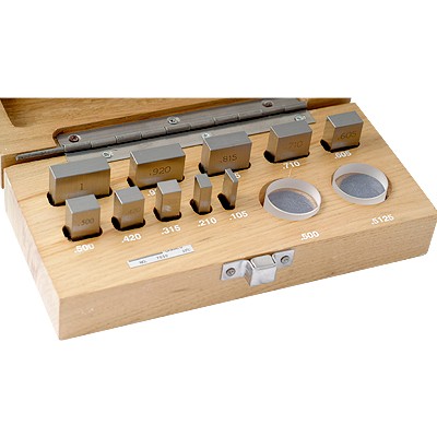
You have two options for achieving these sizes with gage blocks. You can either wring two blocks from your larger set together and achieve the required size, or you can invest in a gage block set that is a Micrometer Checking Gage Block Set and has those sizes already in a single block.
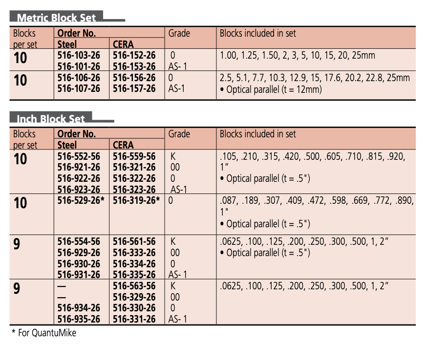
*As a sidebar, the above pictured set is a favorite of mine, available from Penn Tool Co. It’s convenient, accurate, and affordable. A mid to high grade ceramic set is available from InSize at Higher Precision, and if you’re looking for the nicest set, Mitutoyo offers the following options from their catalog:
Now I’ve been asked multiple times, how often do you find a micrometer that is good at zero and full scale but bad at one of these offset points in between? It’s not common at all, but it’s happened to me several times throughout my career, so I feel it’s something that should be checked. Although you can expect the micrometer to look fairly worn if the lead screw is worn and worn unevenly, you still never know and aren’t being paid to guess, so it’s recommended you check those offset points.
Checking the flatness of the anvils is fairly easy as well. You use an optical flat, and are supposed to use a monochromatic light source when checking flatness. I say supposed to because if you are young and have good vision, you can read an optical flat on traditional anvils without the assistance of a monochromatic light source. If I’m checking flatness of say a disc micrometer’s anvils, I would go for the light source because it’s very difficult with that style to see it unassisted. If you need it, use it, if you don’t, have it handy anyway. Experienced technicians can tell you by the finish on the face if it’ll read with an optical flat or not before ever even trying.
Here’s an example from Engineering Technology of a flat on a gage block, which gives you a better view of the fringes. A chart/poster with the specific patterns you might see can be found from Van Keuren.
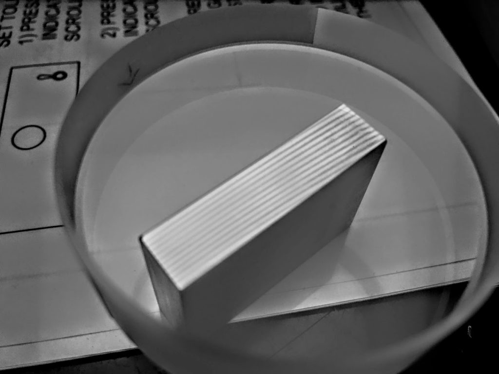
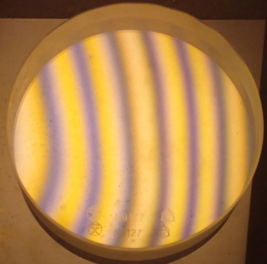
There’ll probably be an article on optical flats themselves coming up shortly, but for now the basic principle is to lay the optical flat on the anvil and view the fringes to see if they’re straight or if they’re curved or distorted. You should something like this. You shouldn’t need to wring the flat to the anvil, so there’s no need scrape the flat up by moving it around too much on the anvil.
So let’s put it all together now in a step by step procedure.
Calibration procedure
- Gather necessary standards, wipe down/clean micrometer, examine micrometer and note any missing or broken parts/features.
- Check that you are repeating at zero.
- Measure the gage blocks at the specific test points necessary to fully check the micrometer, noting any deviations from nominal.
- Inspect both the spindle and stationary anvils for flatness with an optical flat and report any deviation in flatness.
- Ensure that the readings you found are within the stated accuracy of the instrument being tested. If accuracy specifications aren’t available from the manufacturer, use specifications from ASME B89.1.13 as generic/standard tolerances.
- Clean, adjust and if necessary repair micrometer to bring it back into tolerance if it is found out of tolerance. Adjustments would be made with the tenths sleeve on a vernier outside micrometer or resetting the origin on a digital micrometer. There are other things you can do if you have a unique problem with functionality or calibration. Look for a separate article coming up on micrometer maintenance and repair that will go deeper into micrometers.

Leave a comment