The Webster hardness tester is a portable tester for testing materials such as aluminum, brass, copper, and mild steel. It can be used to quickly identify tempers and to quickly test a variety of shapes that can be difficult to check with other testers, including extrusions, tubing and flat stock.
Here’s what a standard kit looks like:
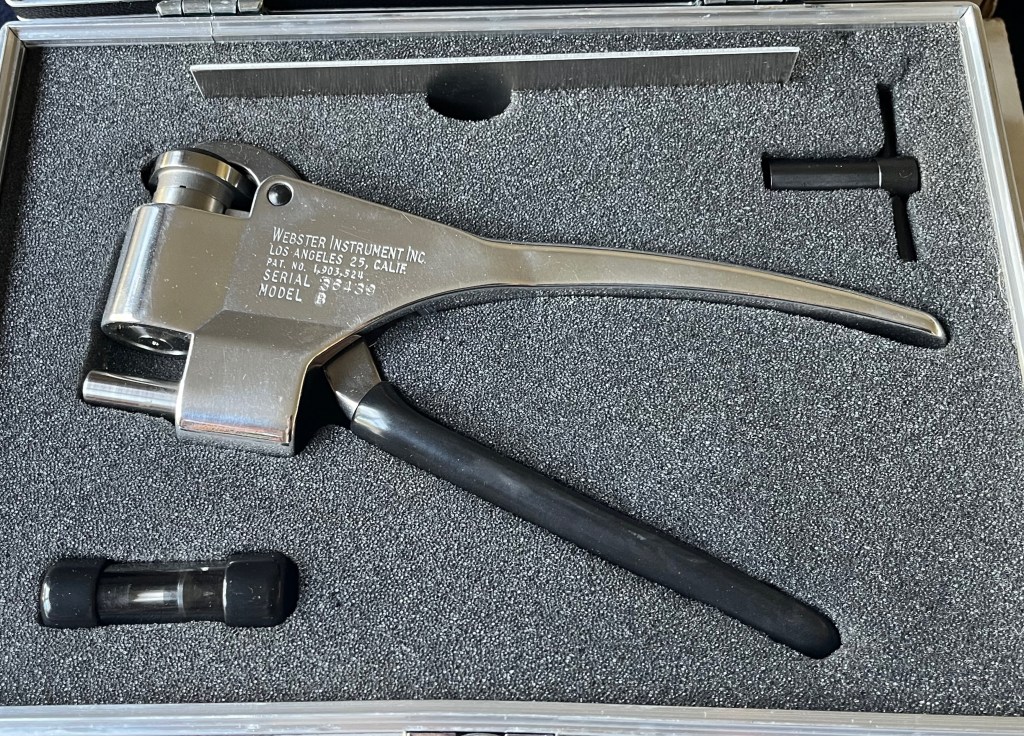
You can see a test strip on top, the adjustment wrench in the top right, a spare indenter in the bottom left, and the tester itself in the middle. Using this tester isn’t much more complicated than using a stapler, just watch the needle and be sure you don’t go over 20 on the scale, or you could bend the dial needle and damage the indicator.
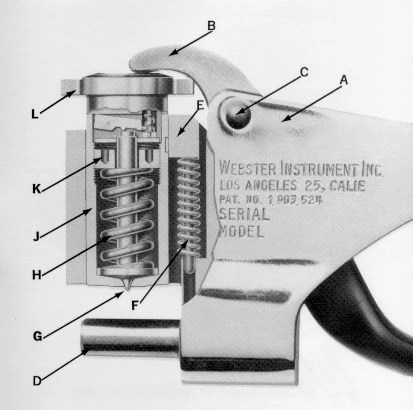
Here we have a cutaway image of the tester. The parts are:
A) Frame
B) Handle
C) Pivot Screw
D) Anvil
E) Housing Key
F) Return Spring
G) Indenter / Penetrator
H) Load Spring
J) Penetrator Housing
K) Adjusting Nut
L) Dial Indicator
Adjustment is simple, but before performing the adjustment you’ll want to check the dial function. Be sure it’s movement is smooth, repeatable, and returns to zero. If not, it may need replacement or repair.
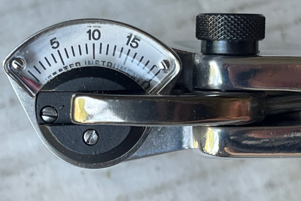
The first step is to check the zero adjustment. The dial needle should be resting on or to the left of the 0 marking on the upper dial numbers. If it isn’t, there’s a problem.
Push down to operate the tester against the bare anvil. This should max out the reading on the dial. Ideally it will stop at the 20 mark at the far right of the dial, which is sometimes marked 20 on top but usually just marked 0 on the bottom of the dial. This is the max of the dial. If it doesn’t stop here automatically, don’t continue to apply pressure, you can bend the needle and cause damage to the indicator. Just because it doesn’t stop at 20, doesn’t mean that it’s broken.
However, if it stops before 20 you’ll need to adjust the small screw on the bottom of the indicator until it reads 20 with pressure applied to the bare anvil. When you let go of the handle, the needle should return to zero give or take a division. If it doesn’t, there’s a problem. When these indicators go bad their range becomes limited.
Some older technicians, and older manuals, will tell you if you do the zero adjustment, and the test strip reads accurately, that you have an accurate tester. This is not true, as it doesn’t take into account the shape and condition of the penetrator. You can grind the point off the penetrator, and still get it to zero and read accurately on the strip if the spring is adjusted to the strip. Multiple points need to be checked to prove linearity.
The idea of the 0-20 scale is to represent and convert to readings on various Rockwell hardness scales that measure within the range of this instrument (charts at bottom of page). So, you should be able to take calibrated standardized Rockwell hardness test blocks and use THEM to calibrate the tester in addition to the above testing. In all of my years of calibrating dozens upon dozens if not hundreds of these testers, I can tell you, if it doesn’t read accurately on Rockwell blocks after I perform the above testing, it’s not going to give you accurate numbers in the field, and I’m going to fail that tester. It needs a new penetrator and/or indicator.
So the procedure I’m recommending for calibration would be:
1) Zero Test
2) Strip Test
3) Rockwell Block Test
This will tell you if you have a good tester and give you the confidence you need to put the tester in use for it’s calibration cycle. The customer should be using a test strip, block, or check standard to verify the tester daily or before use. If they see a deviation or trend, the indenter is likely wearing. If it’s making repeatable readings, and has a repeatable error, you can make an adjustment with some confidence. If in general the repeatability is growing in span, or the error is inconsistent, recalibration with Rockwell blocks is recommended to determine if a new indenter or indicator is needed.
ADJUSTMENT PROCEDURE
So you’re getting bad readings. First step is to disassemble the tester. Remove the black screw on the side of the tester. Push down on the dial and you should be able to pull the handle out. With the handle removed you can now pull up on the dial indicator and remove it from the tester. You should be looking at this:
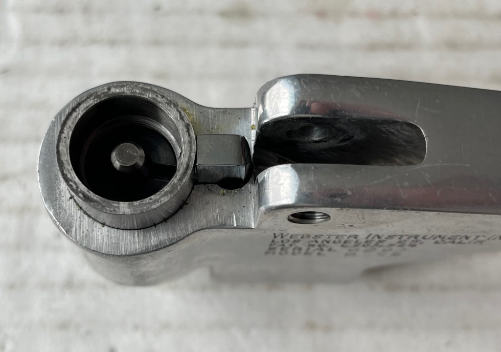
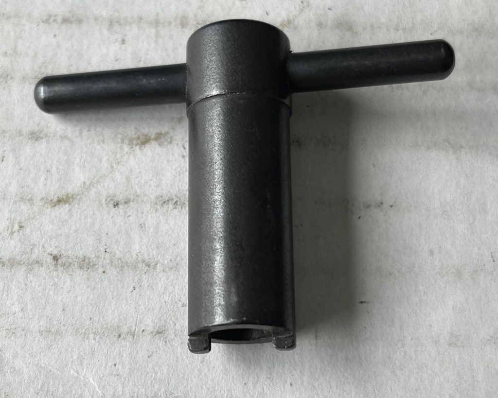
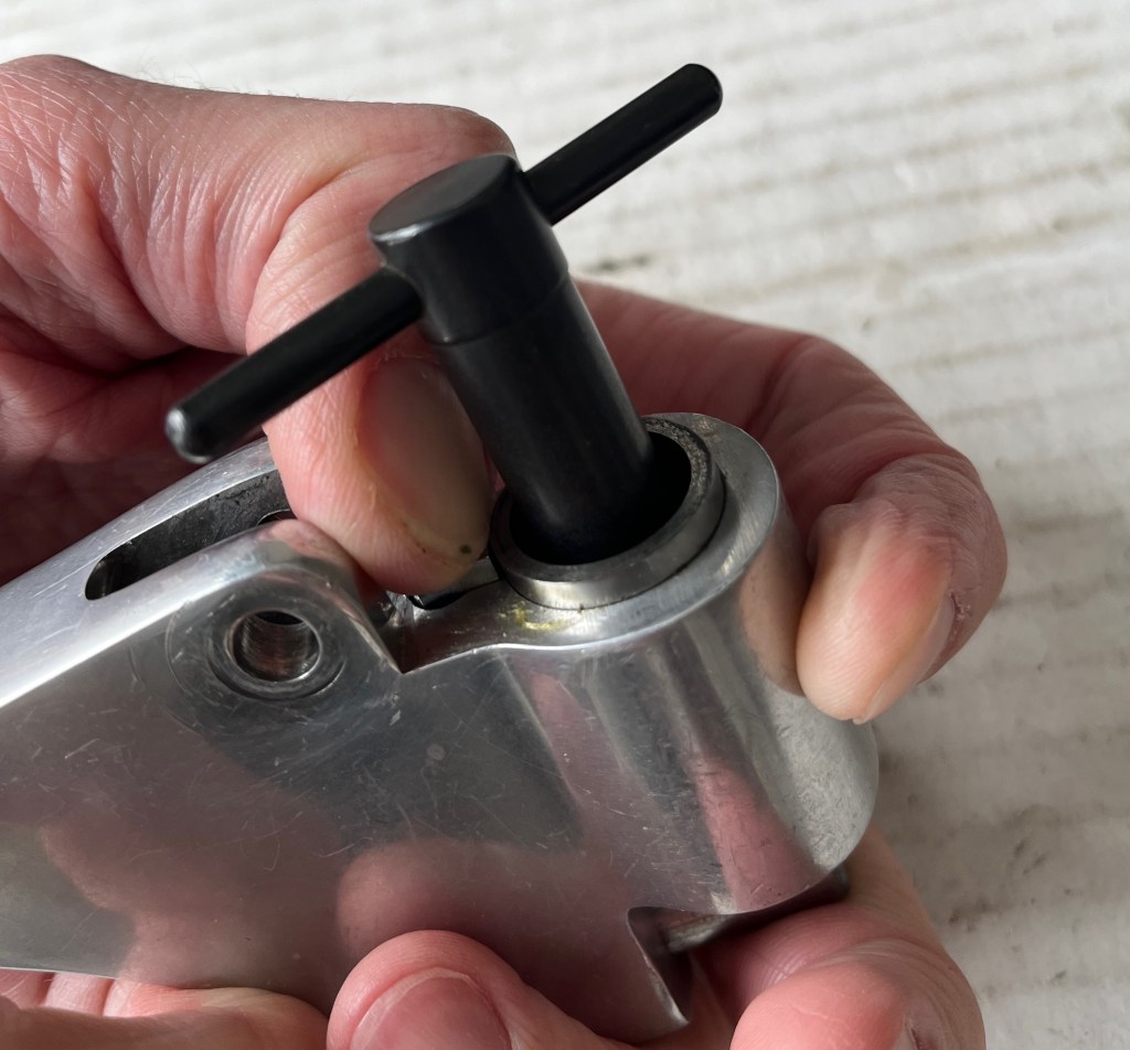
You’ll want to take the provided adjustment wrench, place it in the grooves of the black adjusting nut and turn to adjust. It helps to push down on the penetrator housing so the housing key doesn’t come undone when you twist. Turning clockwise tightens the spring and decreases the dial reading. Turning counter-clockwise will loosen the spring and increase the dial reading.
I adjust testers to the strip included with the kit, just so as not to use up my Rockwell blocks.
Unfortunately it’s a bit of a trial and error process to get the tester reading right where you want it, and you need to re-assemble it to check it in between adjustments.
Start with a quarter turn revolution, it doesn’t take much to change the dial by a point or two.
Once you’ve got the tester reading accurately and repeatably on the strip, and you’ve got yourself a solid and repeatable zero, you can check the tester at multiple points with Rockwell hardness blocks and with any luck you’ll find yourself with an accurate and linear tester.
As far as repairing a non-linear tester, there really isn’t much to these things. You can clean, lightly lubricate, and look for any burrs or raised areas on the housing or anvil that could be causing a problem. Assuming you don’t see anything wrong with the indicator right off the bat, your best bet is to replace the indenter. They can become deformed and lose their point, making them ineffective. If that doesn’t work the next most likely part to be a problem is the indicator. Unfortunately, it can be cost prohibitive to replace the indicator these days, and I’ve found nobody able or willing to repair them. It’s over $500 to get an official indicator from the manufacturer. They do however offer repair services, it’d probably be best to send them the tester for repair evaluation and be sure what you’re dealing with before investing that much money into an attempted repair.
To replace the indenter, the procedure is about the same as making an adjustment to the spring tension. Turn the adjusting nut counterclockwise to loosen spring tension to the point the nut comes off, the spring comes out, and the indenter can be removed. Replace with the new indenter, return the spring, and tighten the spring tension back up by turning the adjusting nut. Re-calibration should always be performed when changing the indenter/penetrator. Indenter can be examined under magnification periodically for deformation.
Resources
(Information and conversion charts)
(Models B, B-75 and BB-75)Download
Webster Instruments Home Page Original Manufacturer Website
Gardco / Paul Gardener Good Second Source for Webster Product


Leave a comment